As the volume of material generally expands after it is removed the cut factor is usually set to greater than 10 indicating swell or expansion. In the Create Volume Surface dialog box do the following.
Civil 3d Volumes Dashboard Vs Composite Volumes Imaginit Civil Solutions Blog
Set the Design Surface from the drop down menu.
Cut fill factor tin volume surface. For the cell above the volume of cut-and-fill is. I have used 110 for cut 125 for rock cut and 115 for fill. It is also possible to apply cut and fill factors.
- 2STA 100 Cut 1 area 85ft2 Fill 1 area 100ft-STA 200 Cut 2 area 140ft2 Fill 2 area 20ft2 Step 2. 1034 CompactionExpansion End-area Volume Use this dialog to specify aggregate cut and fill factors for given materials over a range of stations. Volume Calculations Civil 3D 2014 0315 WI-NRCS.
Im getting some nice cut and fill numbers when I check the. Cut and fill factors in Civil 3D. When caluclating the cut and fill with the factor it.
Cut and Fill Factors - Stratums. The cut and fill results are shown in Panorama. 1 Klik OK Generate CutFill Report Untuk melihat tabel CutFill.
For example a 12 cut factor would mean that for every 10 cubic meter of material removed 12 cubic meters of volume would need to. Menghitung Volume Cut-Fill. Page 2 of 4.
Compensates for the expansion factor of the cut material. Enter the desired Grid Interval. Pilih Surface Final.
The last step consists of checking the volumes. For Name select Earthwork. Use above formula to calculate the cutfill volume between stations - Volume cut 85ft 2140ft 2 x 100ft 11250 ft3.
The raw cut and fill volumes are multiplied by these values to compensate for expansion and compaction of the surface material. Click Recompute Volumes or right-click the surface in the Volumes Dashboard and click Rebuild to update the volumes. Cut and Fill Factors Applied Now simply move your Level surface up and down grab the polyline and use the move command.
Select EXISTING Surface Triangulation File Choose an flt or tin file Select FINAL Surface Triangulation File Choose an flt or tin file Select Inclusion polylines. Figure out total cutfill area per station. TIN stands for Triangulated Irregular Network.
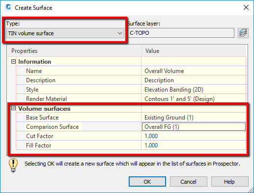
Step 4 Calculate the cubic yards of cut or fill required in each grid cell. For Base Surface select EG. For Comparison Surface select FG Final.
Specify the Surface Type. For Style select _No Display. Fill Factor specifies the fill factor for the surface.
This should be the same or a multiple of the interval used for the template drops when the design surface was created. Fill Adjusted Displays the amount of material that has to be added for the base surface to equal the comparison surface. Note Cut and Fill factor are left at 1000 as Im unsure how these values effect the TIN volume surface.
These are commonly provided in the geotechnical reports. Select the Original Surface from the drop down menu. It is the most common method of interpolating elevations when we are creating a surface.
The project is not balanced and the requirement for extra fill means that. Then on the Statistics tab expand the Volume tree. The style typically used to show CutFill is an Elevation.
I have heard of a site contractor who took the SF of fill area x 17 2 inches divided by 27 and added that yardage to his fill amount. Select the comparison surface typically the newly created surface by clicking in the Value column and clicking the three dots Optional. 17188 ft3 6366yd3 For the cell to the right compute the volume of cut-and-fill Cut and Fill Calculations 12 3 45 1 400 300 300 200 100 2 300 300 200 100 000 3 200 200 100 000 -100 4 200 100 000 -100 -200 5 000 -100 -200 -300 -400 For the cell above the volume of cut-and-fill is.
For this we will use a TIN Volume Surface. CompactionExpansion parameters can override this value for existing surfaces. This allowed for proofrolling at fill areas.
In the Prospector select the surface right-click and go to Surface Properties. Pilih SurfaceVolume pada layar Add Labels Spot Elevation on Grid Specify a grid base point tentukan areakotak untuk menampilkan grid kiri-bawah siteplan. Step 3 Determine elevations at each calculation location the corners of each grid.
A TIN volume surface is created using surface style Contours 1m and 5m design and the existing TIN surface is assigned to the base surface with the proposed TIN surface assigned to the comparison surface. If a Fill Factor is specified it is applied. TINs can be adjusted vertically to provide additional layers sub-grade or Bore log depths In Addition to the TIN option for surfaces 12d Model is string based this allows cross sections to be cut through the design model at any location required.
Components and existing surface use a fill factor. Create a Volume Surface. Here you see that the Cut Volume value is much smaller than the Fill Volume value.
While using the Grid Volume Method for producing Cut and Fills we wanted to include the volume correction factor of 085 for fill fill will campact to only 85 of what is used. - STA 100 Cut 1 area 85ft2 Fill 1 area 100ft2 - STA 200 Cut 2 area 140ft 2 Fill 2 area 20ft Step 2. Type a cut factor and a fill factor for the Composite Volumes Corrections values.
If using a fence set the Fence Mode with the drop down menu. This parameter also known as the compaction factor defines how much the volume of the fill material will decrease after it is placed into the site. Example a value of 08 means that the fill material will shrink to 08 times its original volume.
This is usually given. A factor of 100 does not adjust the volumes. For Volume Calculations 2d or 3d data can be draped onto a TIN to match the model levels.
He then added 15 to the total. In either case the volume is calculated by multiplying the cut or fill depth by the area of the grid cell. Name your surface and set a style.
To figure out what is the total net cutfill between station 100 and 200. Adjust the cut or fill factor to account for extra loss or compaction Click OK. The cut or fill depth for each cell is found by subtracting the average existing level of the cell from the average proposed level.
Required than cut or a blend cut and fill about equal Step 2 Determine the pattern of calculation points or grid size. The volume dashboard will give us the amount of cut and fill in the volume surface as well as the net volume the difference between cut and fill so that we know whether the project will have an excess of material net cut or will have to import material net fill. Notice the adjusted and unadjusted Cut Volumes.
Step 5 Add the individual Grid Cell quantities together to arrive at the total cut total fill volume and the import or volume export. Select Evaluation Volumes Grid Volume from the InRoads menu. Figure out total cutfill area per station.
2 Volume 625 4 ft. This value is 10 by default which does no adjustment. Applied to the fill volume.
Use above formula to calculate the cutfill volume between stations - Volume cut. Thisis done from the surfaces statistics. If the resultant depth is positive then this is a fill cell while a negative value indicates a cut cell.
Fill Factor 10001000 - shrink_percentage using 15 shrink as an example Fill Factor 10001000 - 150 117647. Well the volume dashboard allows you to apply different cut and fill factors so to prevent the volumes above the level surface from being used simply set the cut or fill factor for that portion to zero. This is usually given.


